Battery Management Systems
Table of Contents
Introduction
In some systems, it’s desirable to have good knowledge of the battery charge level. This value is commonly known as the battery state of charge (SOC).
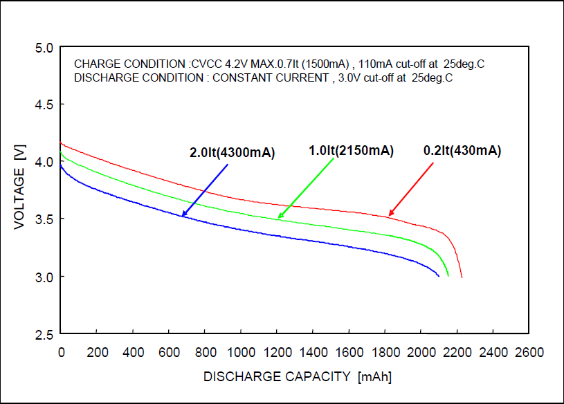
Below is a graph of typical cell voltage vs capacity. The actual SOC does not have a linear relationship with the voltage.
Batteries providing a SOC value give a more accurate estimation of the remaining capacity.
The SOC data can be used for multiple purposes:
- Reduce the power available to the motor to extend the range at the expense of power and performance, but only when the battery SOC is low.
- Display SOC estimates to inform a rider how fast the battery is depleting and how much capacity is left before running out of power.
- Override existing external BMS (battery management system) low and high voltage behaviours.
BMS setup
The Battery management interface type options are listed below. If voltage model, network (LIN/Modbus) or analog BMS signal is not present an internal software Voltage Model can be set up to linearize and estimate a battery’s SOC.
- 0 is none
- 1 is voltage model
- Controller side SOC calculation, see instructions below for setup
- 2 is analog 10V
- Uses ABMS input
- 4 is LIN
- 5 is ModBus
- TTL or CAN
If none is selected the SOC will always read 100%. In this case, voltage foldback parameters should be configured to protect the system. If SOC
Remote BMS
Typical values sent by the BMS over network include:
- Battery voltage
- Battery current
- Battery SOC
- Battery temperature
Voltage model setup
A simplified way of interpreting the battery voltage to understand how much capacity the battery has left is to reinterpret the battery voltage as a state of charge (SOC), where a fully charged battery’s SOC will read 100%, and a dead battery’s SOC is 0%.
(SOC) gain and offset calculator
The calculator below can be used to help set up the characteristics of the voltage model.
| Enter nominal battery voltage | Battery rated voltage, ie. 36V, 48V etc. Should use same value as Rated system voltage | |
| Enter 100% state of charge voltage | Fully charged battery voltage | |
| Enter 0% state of charge voltage | Battery manufacturer's minimum operating voltage |
The state of charge in percent can be calculated using the following formula. Note that on the controller, the formula is limited to the upper limit of 100% and a lower limit of 0%.
SOC = ((battery voltage / Rated system voltage) * Voltage model battery state of charge gain) + Voltage model battery state of charge offset
Battery resistance
Battery resistance helps the Voltage Model compensate for large currents through the battery system and its connections through the controller. It can be calculated with the following method.
- Read the “no-load” battery voltage (ideally for a fully charged battery).
- Using a bike trainer or actually riding under heavy load (ideally full load), simultaneously read the battery current and battery voltage values from BacDoor™.
- Battery resistance = (“no load “ battery voltage – “full load” battery voltage) / “full load” battery current. The value is usually around 200 milliohms.
- Enter this value in parameter Battery resistance.
SOC model verification
To test validity, you need to be able to modify the battery voltage while observing the SOC value. You can see the SOC value in BACDoor™ through the parameter called ‘battery state of charge’. You could use an adjustable power supply to modify the system voltage between full and empty charges. You will need to wait for several minutes after adjusting the voltage before it’s reflected in the parameter.
More likely, you’ll want to use a display, which should be tested by riding the bike until the battery is empty.
Configuration parameters
Battery configuration parameters
| Name | Description | Units | Address |
| 70 | |||
| 155 | |||
| 209 |
Voltage model configuration
| Name | Description | Units | Address |
| 197 | |||
| 198 | |||
| 59 |
Battery limiters
| Name | Description | Units | Address |
| 290 | |||
| 310 | |||
| 324 | |||
| 317 | |||
| 386 | |||
| 379 |